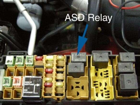
Relay - Function - Failure - Testing")
The function of the automatic shutdown (ASD) relay, is to shut off power to major systems. When the key is turned off, as a safety feature.
So, when the automatic shutdown (ASD) relay is on. It supplies battery voltage (12+ volts) to the fuel injectors, and ignition coil(s).
And, with certain emissions packages it also supplies (12+ volts). To the oxygen sensor (O2) heating elements, and the oxygen (O2) sensor heater relay.
So, the ground circuit within the Automatic Shutdown (ASD) relay, is controlled by the (PCM). Consequently, the (PCM) operates the (ASD) relay, by switching its ground circuit ON and OFF.
Then, the (ASD) relay will be shut-down. And, that means the 12-volt power supply to the (ASD) relay will be deactivated by the (PCM). As a result, of the ignition key being left in the ON position. But, only if the engine has not been running, for approximately 1.8 seconds.
Basically, the (ASD) relay is responsible for supplying, switched 12-volt power to the:
- Fuel injectors
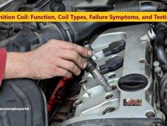
- Ignition coils
- Oxygen sensor heater elements
- Oxygen sensor heater relay
Common Symptoms, Of A Failing Automatic Shutdown (ASD) Relay
Well, as with most electrical components, the (ASD) relay is subject to normal wear and tear. So, when it fails it can cause problems for the entire vehicle. Usually, when the (ASD) relay has failed or is having a problem, the vehicle will produce a few failure symptoms.
ENGINE STARTS, BUT, STALLS
One of the most common symptoms of a bad (ASD) relay, is an engine that will start. But, stalls almost immediately, or at random times. The (ASD) relay supplies power to the vehicle’s, ignition coils and fuel injectors. Certainly, the most important components, of the entire engine management system.
If the (ASD) is having any problems that interfere with its ability to supply power. Then, those components may not function properly, and problems may arise. Including, the injectors, coils, or whatever other circuits it may feed. A vehicle with a failing or faulty (ASD) relay, may stall immediately after starting, or randomly while operating.
ENGINE WILL NOT CRANK
Another symptom of bad (ASD) relay is, an engine that will not crank at all. Because, many of the engine management systems are wired together.
So, if any of the circuits that the (ASD) relay provides power for go out, as a result of a bad (ASD) relay. Then, it may affect other circuits, one of them being the starting circuit.
A bad (ASD) relay can indirectly, and sometimes directly, cause a starting circuit to not have power. And, can result in a no crank condition, when you turn the key.
CHECK ENGINE LIGHT (CEL), COMES ON
Another symptom of a possible problem with the (ASD) relay is, an illuminated (CEL). So, if the computer detects that a problem with the (ASD) relay or circuit has occurred. Then, it will illuminate the (CEL), to alert the driver of a problem. But, the (CEL) can also be activated, for a wide variety of other reasons. Above all, it is important to have the vehicle scanned for trouble codes. Because, it will help you determine what the exact cause of the problem may be.
CLICKING NOISE, COMING FROM AUTOMATIC SHUTDOWN (ASD) RELAY ( COMMON ON JEEP)
Most likely the clicking noise is, because, there wasn’t enough voltage going to the relays, to engage them. As a result, the (ECU), was detecting a low battery condition, even though it had a good battery.
Another symptom may be that the vehicle would start up immediately, when boosted. But, as soon as the ground jumper was removed, the engine died, and the relays started clicking again.
Also, there is a somewhat common problem with wires breaking, due to acid from the battery. Sometimes, both the (PCM) and fuse panel wiring, are under the battery. Potentially, causing an (ASD) ground control wire to break, between the (PCM) and the fuse panel.
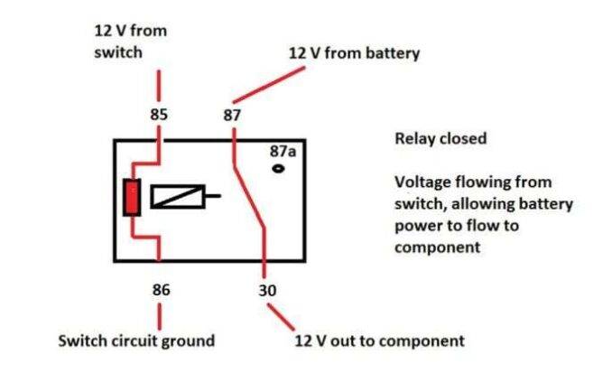
The (ASD) Relay Actually Functions, (just like a fuel pump relay)
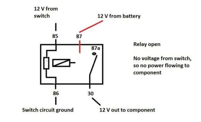
- Terminal number 30, is connected to battery voltage. For both the (ASD) and fuel pump relays, terminal 30 is connected to battery voltage at all times.
- The (PCM) grounds the coil side of the relay, through terminal number 85.
- Terminal number 86, supplies voltage to the coil side of the relay.
- When the (PCM) de-energizes the (ASD) and fuel pump relays, terminal number 87A connects to terminal 30. This is the OFF position.
- In the OFF position, voltage is not supplied to the rest of the circuit. Terminal 87A is the center terminal on the relay.
- When the (PCM) energizes the (ASD) and fuel pump relays, terminal 87 connects to terminal 30. This is the ON position. As a result, terminal 87 supplies voltage to the rest of the circuit.
So, How Do You Test, An Automatic Shutdown (ASD) Relay
(ASD) Relay Testing, With An Ohmmeter:
- Remove the relay from the connector, before Testing. With the relay removed from the vehicle, use an ohmmeter to check the resistance between, terminals 85 and 86. The resistance should be, 75 ohms 5 ohms.
- Connect the ohmmeter between, terminals 30 and 87A. The ohmmeter should show continuity between, terminals 30 and 87A.
- Connect the ohmmeter between, terminals 87 and 30. The ohmmeter should not show continuity at this time.
- Connect one end of a jumper wire (16 gauge or smaller) to relay, terminal 85. Then, connect the other end of the jumper wire, to the ground side of a 12-volt power source.
- Connect one end of another jumper wire (16 gauge or smaller), to the power side of the 12-volt power source. Do not attach the other end of the jumper wire to the relay at this time.
WARNING – Do NOT allow ohmmeter to contact terminals 85 or 86 during this test. Damage to the ohmmeter may result.
- Attach the other end of the jumper wire to relay, terminal 86. This activates the relay. The ohmmeter should now show continuity between relay, terminals 87 and 30. The ohmmeter should not show continuity, between relay terminals, 87A and 30.
- Disconnect jumper wires. Replace the relay if it did not pass the continuity and resistance tests. If the relay passed the tests, it operates properly. Check the remainder of the (ASD) and fuel pump relay circuits.
(ASD) Relay Testing, With A Test Light:
- Find the particular relay you want to test. Depending on the circuit it controls, the relay may be located under the dashboard. Or, inside the engine compartment, in a junction block.
- Turn the ignition switch on to energize the particular circuit you are testing, if necessary.
- Connect the alligator clip from a test light, to any good ground on your vehicle. Probe the wire coming out of the relay and going to the component, with the tip of the test light. If the bulb in the test light glows, there is voltage, and your relay is working properly.
- Probe the wire or wires feeding voltage to the relay with the test light. And, following the same procedure used on the previous step. If the light glows, there is incoming voltage. Otherwise, the relay is not receiving voltage. Check the voltage source.
Switch the ignition key off. Unplug the relay from its electrical connector, making sure not to break the locking tabs on the relay.
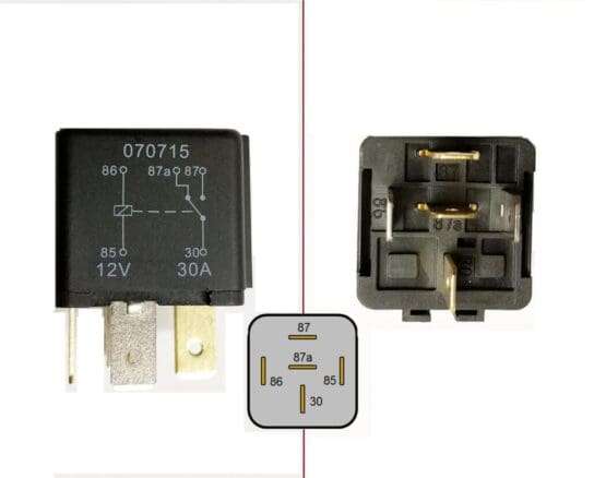
- Identify the relay’s power and control terminals. Some relays show a circuit diagram on top of the case to identify these terminals.
- Check for continuity between the two power terminals using an ohmmeter. There should be no continuity. If there is continuity, replace the relay.
- Connect a jumper wire between, the battery positive terminal, and one of the control circuit terminals on the relay.
- Connect the other control terminal to ground with another jumper wire. If you do not hear a click as you make the second connection, reverse the connections. If you still do not hear a click, replace the relay.
- Connect the jumper wires as you did on the previous step. Using an ohmmeter, check for continuity, between the two power terminals. If there is continuity, the relay is working properly. Otherwise, replace the relay.
Conclusion
Check for severe corrosion on the (ASD) relay socket terminals. Check for broken wires under the (ASD) main relay box. If you don’t see ground, from the (PCM) in the socket. Then, check for ground on the brown/white wire coming from the (PCM). Finally, if you still don’t see ground, and you don’t have an anti-theft issue. Then, you may have a bad ignition switch.