Crankshaft Thrust Bearing Failure - Causes And Remedies
For years, both transmission and engine rebuilders, have struggled at times, to determine the cause, of crankshaft thrust bearing failure.
Diagnosing a crankshaft thrust bearing failure, can sometimes be simple, but often is tricky. And, chances are, the problem is more likely to occur, with an automatic transmission setup.
Consequently, when a crankshaft thrust bearing failure is discovered, it’s usually too late. Because, the damage has been done to the thrust bearing itself and likely, to the crankshaft as well.
The causes of a crankshaft thrust bearing failure, can be traced to a single problem or a combination of problems.
Crankshaft Thrust Bearing Failure History
So, thrust bearings run on a thin film of oil just like radial journal (connecting rod and main) bearings. But, they cannot support nearly as much load. And, radial bearings can carry loads measured in thousandsof pounds per square inch of projected bearing area. But, thrust bearings can only support loads of a few hundred pounds per square inch. Radial journal bearings have a higher load capacity. Consequently, from the way the curved surfaces of the bearing and journal meet to form a wedge.
Furthermore, shaft rotation pulls oil into this wedge shaped area of the clearance space to create an oil film. And, that actually supports the shaft. Thrust bearings typically consist of two flat mating surfaces. But, do not have a natural wedge shape in the clearance space. Therefore, can not promote the formation of an oil film to support the load.
For this reason, many heavy-duty diesel engines use separate thrust washers. And, have a contoured face to enable them to support higher thrust loads. These thrust washers have multiple tapered ramps and relatively small flat pads. And, can have curved surfaces that follow a sine-wave contour around their circumference.
Causes Of Crankshaft Thrust Bearing Failure
So, there are only four common factors which generally cause crankshaft thrust bearing failures.
And, these are:
Poor crankshaft, surface finish.
Misalignment.
Overloading.
Surface finish.
Most of the time, crankshaft thrust faces are difficult to grind. Because, they are done, using the side of the grinding wheel. Consequently, grinding marks left on the crankshaft face, produce a visual swirl or sunburst pattern with scratches. Also, crisscrossing one another in a cross-hatch pattern, similar to hone marks on a cylinder wall. So, these grinding marks need to be completely removed by polishing.
If not, they will remove the oil film from the surface of the thrust bearing. A properly finished crankshaft thrust face, should only have very fine polishing marks. And, go around the thrust surface, in a circumferential pattern. Also, shot peening, can dramatically increase a crankshaft’s life. So, it may be a good idea, to look into this.
Alignment
So, a grinding wheel that does not cut cleanly, may create hot spots on the crankshaft. And, lead to a wavy, out-of-flat surface. The side of the wheel must be dressed, at exactly 90° to its outside diameter. This will produce a thrust face, that is square to the axis, of the main bearing journal.
So, the crankshaft grinding wheel, must be fed into the thrust face very slowly. And, also be allowed to “spark out” completely. The machinist should be very careful, to only remove minimal stock, for a “clean-up” of the crankshaft surface.
In most instances a remanufactured crankshaft does not require grinding of the thrust face(s). As a result, the grinding wheel, will not even contact them. But, oversize thrust bearings do exist.
Grinding crankshaft thrust faces, requires detailed attention during the procedure. For instance, repeated wheel dressings may be required. Also, maintaining sufficient coolant between the grinding wheel and thrust surface. Because, this will prevent stone loading and “burn” spots on the thrust surface.
All thrust surface grinding should end in a complete “spark out”. Before, the grinding wheel is moved away from the area being ground. Finally, following the above procedures with care should maintain a thrust surface that is 90° to the crankshaft centerline.
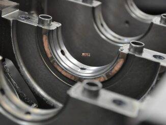
Crankshaft Thrust Bearing Assembly
Tighten the main cap bolts to approximately 10 to 15 ft.lb. to seat the bearing. Then, loosen them:
Tap the main cap toward the rear of engine, with a soft faced hammer.
Tighten the main cap bolts, finger tight.
Using a pry bar, force the crankshaft, as far forward in the block as possible. This will align the bearing rear thrust faces.
While holding the crank in the forward position, tighten the main cap bolts, to 10 to 15 ft. lbs.
Complete torquing the main cap bolts to specs, in 2 or 3 equal steps.
The above procedure should align the bearing thrust faces with the crankshaft. And, also maximize the amount of bearing area in contact for load carrying.
Overloading
A number of factors may contribute to wear and overloading of a thrust bearing:
Poor crankshaft surface finish.
Poor crankshaft surface geometry.
External overloading due to.
Too much torque converter pressure.
Improper throw out bearing adjustment.
Riding the clutch pedal.
Too much rearward crankshaft load pressure, due to a malfunctioning front mounted accessory drive.
Also, there are other common problems:
Torque converter ballooning.
The wrong flexplate bolts.
The wrong torque converter.
Pump gears, being installed backward.
All of these problems will cause, undue force on the crankshaft thrust surface. It will also cause the same undue force on the pump gears. Because, all of these problems result in the pump gear pushing on the crankshaft, via the torque converter. The result is serious pump damage in a very short period of time (within minutes or hours). So, to help prevent any further damage you should make sure to look after your torque converter as well.
Crankshaft Thrust Bearing Failure, Diagnosing The Problem
So, by the time a crankshaft thrust bearing failure becomes evident, the parts are already been badly damaged. As a result, there is little, if any evidence of the cause. At this point the steel backing of the bearing is now visible. And, has badly worn the crankshaft thrust face. So, how do you tell what happened? Start by looking for the most obvious, internal sources.
Engine Related Problems
Is there evidence of distress anywhere else in the engine that would indicate a lubrication problem or foreign particle contamination:
If the thrust bearing is in an end position, is the adjacent oil seal installed correctly? An incorrectly installed rope seal, can cause sufficient heat, to disrupt bearing lubrication.
Examine the front thrust face on the crankshaft, for surface finish and geometry. This may give an indication, of the original quality of the failed face.
Crankshaft Thrust Bearing Failure, Transmission Related
Did the engine have a prior crankshaft thrust bearing failure:
Were there any external parts replaced?
Did the transmission, have any performance modifications done to it?
So, How Does The Torque Converter, Exert Force On The Crankshaft
There are many theories on this subject, ranging from converter ballooning, to spline lock. But, most of these theories have little real bases and rely little on fact. The force on the crankshaft from the torque converter is simple. It is the same principle as a servo piston or any other hydraulic part. Pressure multiplied by area equals force.
The pressure part is easy, it’s simply the internal torque converter pressure. But, the area is a little trickier. It is the difference between the area of the front half of the converter and the rear half. The oil pressure does exert a force that tries to expand the converter like a balloon. But, it is the fact that the front of the converter has more surface area than the rear. And, that causes the forward force on the crankshaft.
Causes For, Too Much Torque Converter Pressure
So, there are two main causes for too much torque converter pressure:
Restrictions in the cooler circuit.
Modifications or malfunctions, that result in high line pressure.
One step for combating restrictions in the cooler circuit is to run larger cooler lines. Another, is to install any added cooler, in parallel, as opposed to in series.
Modifications that can result in higher than normal converter pressure:
Using an overly-heavy pressure regulator spring.
Too much cross-drilling, into the cooler charge circuit.
Control problems, such as, a missing vacuum line or stuck modulator valve, can also cause high pressure.
Always find the cause of distress and correct it before completing repairs, or you risk a repeat failure.
A simple modification to the upper thrust bearing may be helpful in some engines. Install the upper thrust bearing in the block to determine, which thrust face is toward the rear of the engine. Using a small fine tooth, flat file, increase the amount of chamfer, to approximately .040″ (1 mm). On the (ID) edge, of the bearing parting line.
Finally, carefully file at the centrally located oil groove, stroke the file at an angle. And, only toward the rear thrust face. Above all, it is very important not to contact the bearing surface, with the end of the file. The resulting enlarged (ID) chamfer, will allow pressurized engine oil from the pre-existing groove, to reach the loaded thrust face.
As a result, this added source of oiling, will reach the loaded thrust face. And, without passing through the bearing clearance first (direct oiling). Finally, engine bearings can last a long time, but, they do need to be working perfectly.
After all this, someone decided that there was a need for “anti-ballooning plates”!
In Summary: Crankshaft Thrust Bearing Failure
Special Thanks to, Lance Wiggins and ATRA for Great Information !
So, engine oil consumption, is now going up, as the oil change intervals, become higher. But, most modern engines, don’t suffer from, engine oil consumption. That’s why, many vehicle owners, forget to regularly check their —READ-MORE
You may have heard the term, valve job, because older engines frequently needed their valves reconditioned. You rarely hear about, valve problems or valve jobs in today’s engines. Because, modern (OHC) engines, have fewer parts —READ-MORE
Engine bearing replacement, is really not as hard as it sounds. So, if you have a bearing failure, learning how to replace engine bearings, can save you a ton of money. Consequently, doing your own —READ-MORE
We use cookies on our website to give you the most relevant experience by remembering your preferences and repeat visits. By clicking “Accept”, you consent to the use of ALL the cookies.
This website uses cookies to improve your experience while you navigate through the website. Out of these cookies, the cookies that are categorized as necessary are stored on your browser as they are essential for the working of basic functionalities of the website. We also use third-party cookies that help us analyze and understand how you use this website. These cookies will be stored in your browser only with your consent. You also have the option to opt-out of these cookies. But opting out of some of these cookies may have an effect on your browsing experience.
Necessary cookies are absolutely essential for the website to function properly. This category only includes cookies that ensures basic functionalities and security features of the website. These cookies do not store any personal information.
Any cookies that may not be particularly necessary for the website to function and is used specifically to collect user personal data via analytics, ads, other embedded contents are termed as non-necessary cookies. It is mandatory to procure user consent prior to running these cookies on your website.